Enterprise Network Topologies: Technical Architectural Comparison, Trade-offs, and Mapping Frameworks
Advertisement
Enterprise Network Topologies: Technical Architectural Comparison, Trade-offs, and Mapping Frameworks
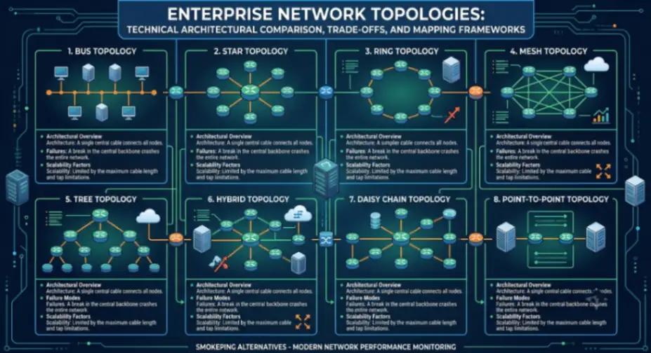
Designing modern enterprise networks requires evaluating structural resilience against deterministic transmission constraints and single-point-of-failure risks. As specified in standards published by the IEEE, physical layer link integrity and media access control directly dictate maximum throughput, collision domain boundaries, and signal degradation limits. Implementing automated network mapping tools like Paessler PRTG Network Monitor enables real-time dynamic visualization and topology-aware dependency graphing across hybrid physical, virtualized, and cloud environment layers.
1. Bus Topology
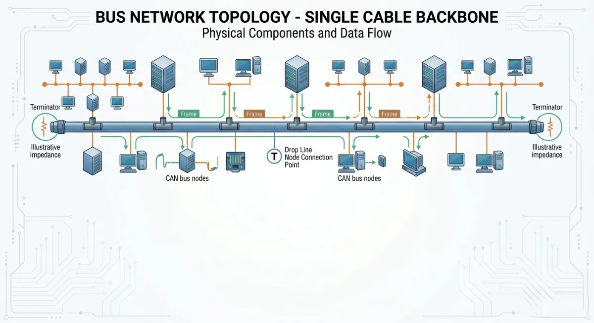
Bus topology relies on a shared physical coaxial backbone cable terminated at both ends to facilitate half-duplex baseband transmissions across connected nodes. Tap connections along the bus allow endpoints to broadcast frames directly to the media, requiring CSMA/CD mechanisms to resolve frame collisions and transmission domain contention.
- Probing & Telemetry APIs: Passive physical layer signal degradation monitoring via SNMP interface counters and TDR (Time-Domain Reflectometry) diagnostic telemetry.
- Anomaly Engine: Static signal reflection threshold detection to identify cable break locations and missing impedance terminators.
- Deployment Model: Legacy industrial serial bus networks (e.g., CAN bus, RS-485) and specialized legacy low-cost local area environments.
2. Star Topology
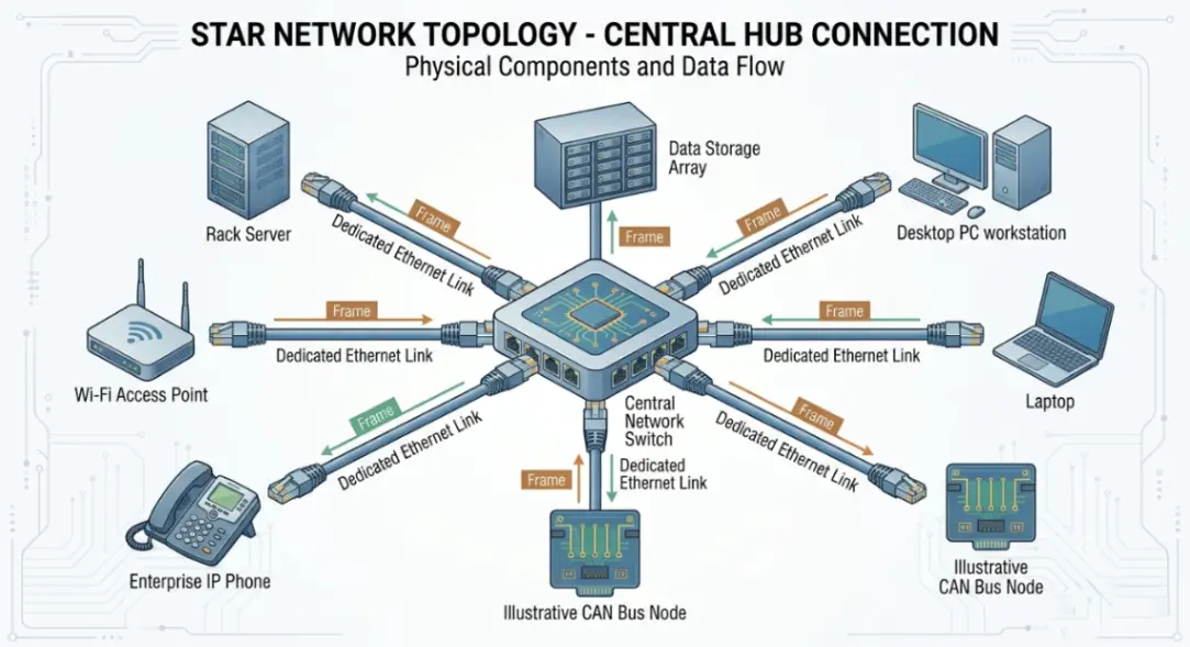
Star topology connects all distributed network nodes directly to a central switching device or hub using dedicated point-to-point links. The central hub/switch orchestrates frame forwarding and micro-segmentation, isolating single-link failures from disrupting adjacent host node communications.
- Probing & Telemetry APIs: Native REST and gNMI/NETCONF streaming telemetry interfaces for real-time switch port status, throughput, and error frame extraction.
- Anomaly Engine: Predictive link failure models evaluating CRC error rates, optical transceiver RX/TX power levels, and buffer drop counters.
- Deployment Model: Universal standard for modern enterprise Ethernet LANs, data center access-layer topologies, and structured cabling drops.
3. Ring Topology
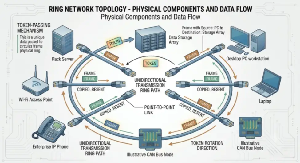
Ring topology arranges network nodes in a closed circular data path where each device connects directly to two adjacent neighbors. Packets travel unidirectionally or bidirectionally using token-passing schemes or ring-wrapping mechanisms to prevent media contention and guarantee bounded access latency.
- Probing & Telemetry APIs: Optical Supervisory Channel (OSC) telemetry and ITU-T G.8032 ERPS (Ethernet Ring Protection Switching) status management APIs.
- Anomaly Engine: Millisecond-level optical signal loss detection triggering automated sub-50ms ring deflection rerouting.
- Deployment Model: Metropolitan Area Networks (MANs), Carrier Ethernet infrastructure, and industrial fiber ring backbones.
4. Mesh Topology (Full & Partial)
Mesh topology establishes redundant point-to-point physical or logical links across nodes, configured as fully meshed (every node connects to all others) or partially meshed (critical nodes maintain multiple connections). Data pathing leverages routing protocols like OSPF, IS-IS, or BGP to compute optimal routes and dynamically re-path around failed nodes.
- Probing & Telemetry APIs: Link-state routing database APIs, eBPF network tracing agents, and OpenFlow controller telemetry bindings.
- Anomaly Engine: Graph-based topology path analysis models calculating real-time dynamic reroute converging speeds and link availability matrix scores.
- Deployment Model: High-availability enterprise WAN backbones, software-defined SD-WAN fabrics, and core data center fabric meshes.
5. Tree Topology (Hierarchical)
Tree topology integrates multiple star topologies onto a bus or hierarchical trunk backbone, creating a structured branching node hierarchy. Divided into core, distribution, and access tiers, it isolates broadcast domains and streamlines centralized management across large multi-tier physical sites.
- Probing & Telemetry APIs: Layer 2/3 topology discovery APIs incorporating LLDP, CDP, and SNMP MIB data extraction.
- Anomaly Engine: Machine learning hierarchy tree models pinpointing root-node failures to prevent downstream dependency alert storms.
- Deployment Model: Multi-building enterprise campus backbones, structured enterprise branch offices, and educational institution networks.
6. Hybrid Topology
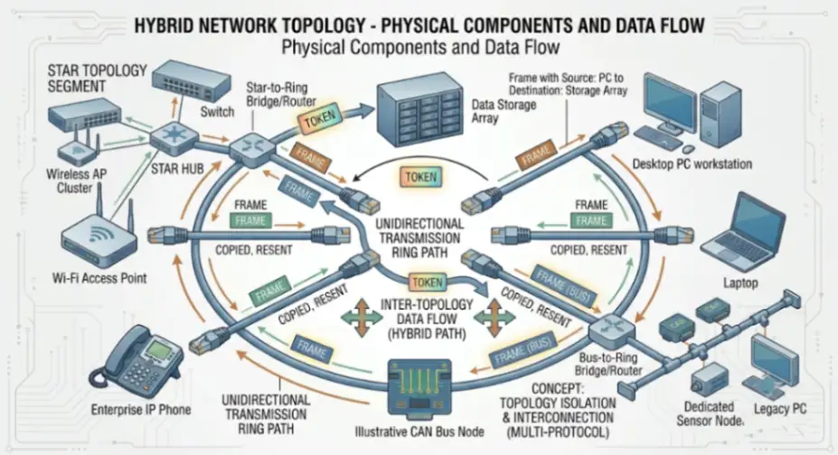
Hybrid topology combines two or more distinct topological structures (such as star-ring or star-mesh combinations) to satisfy diverse geographic, throughput, and redundancy parameters within a unified network architecture. It allows system architects to customize tier-specific failure domains while maintaining inter-segment connectivity.
- Probing & Telemetry APIs: Multi-protocol abstraction APIs bridging REST, gRPC, SNMP, and WMI telemetry across heterogeneous vendor hardware.
- Anomaly Engine: Cross-layer topology correlation engines identifying inter-domain performance degradation and cross-segment routing loops.
- Deployment Model: Multi-region cloud-hybrid enterprise architectures, large-scale industrial IoT deployments, and ISP infrastructure networks.
7. Daisy Chain Topology
Daisy chain topology connects network nodes sequentially in a linear chain or closed loop via direct node-to-node links. Packets pass down the line through intermediate nodes until reaching the target destination, keeping deployment simple without requiring a central switch at every node drop.
- Probing & Telemetry APIs: Serial link diagnostic APIs and embedded host switch controller status hooks.
- Anomaly Engine: Simple continuous link-beat loss detection alerting administrators to broken downstream propagation chains.
- Deployment Model: Industrial automation lines, daisy-chained IP phones/cameras, and cascaded peripheral system networks.
8. Point-to-Point Topology
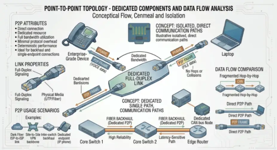
Point-to-Point topology provides a dedicated, unshared physical or logical communications link exclusively between two network endpoints. This direct connection guarantees dedicated bandwidth, minimal protocol overhead, and direct path security for mission-critical link connections.
- Probing & Telemetry APIs: HDLC, PPP, or direct interface MAC/PHY register polling APIs over optical/microwave controllers.
- Anomaly Engine: Strict deterministic latency tracking engines alerting on microsecond-level timing deviations and signal-to-noise ratio drops.
- Deployment Model: Inter-datacenter dark fiber connections, microwave backhaul links, and site-to-site VPN tunnel backbones.
Frequently Asked Questions
What is the primary difference between a physical network topology and a logical network topology?
Physical topology defines the actual hardware layout, cable routing, and interface connections across network devices. Logical topology describes the internal pathing mechanism, protocol rules, and frame transmission flow used by data packets across that physical structure (e.g., physical star running a logical bus or ring).
Why is Full Mesh topology rarely implemented across large-scale enterprise local area networks?
Full Mesh requires every node to connect directly to every other node, resulting in a physical cable/link equation of N(N-1)/2. For large networks, the cost, port density requirements, and configuration complexity scale exponentially, making partial mesh or hierarchical tree topologies far more cost-effective for LANs.
How do dynamic topology mapping tools discover complex hybrid network layouts?
Modern discovery engines combine Layer 2 protocol probing (LLDP, CDP) with Layer 3 IP routing table analysis, SNMP queries, and ICMP/traceroute probing. By correlating MAC tables, ARP caches, and link-state databases, these platforms automatically map dependencies and physical link connections in real time.
Advertisement