Enterprise Layer 2 Protocols: Architectural Overview & Network Operations Guide
Advertisement
Enterprise Layer 2 Protocols: Architectural Overview & Network Operations Guide
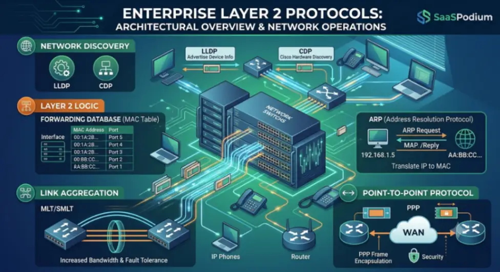
Modern enterprise networking relies on Data Link Layer mechanisms to bridge physical media signaling with network-layer IP routing. Governed by standards organizations such as the IEEE Standards Association, Layer 2 protocols encapsulate network packets into structured Ethernet frames, performing cyclic redundancy checks (CRC) and collision handling to guarantee physical link transport integrity.
1. Link Layer Discovery Protocol (LLDP)
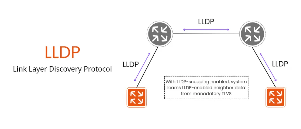
Link Layer Discovery Protocol (LLDP) is a vendor-neutral, IEEE 802.1AB-standardized protocol that enables network devices to advertise identity, capabilities, and neighbor topologies across local Ethernet segments. Operating directly over Ethernet frame type 0x88CC, LLDP populates local Management Information Bases (MIBs) to enable automated topology mapping and infrastructure observability.
- TLV Frame Structure: Encapsulates device attributes using Type-Length-Value (TLV) structures, broadcasting system names, management IP addresses, port IDs, and Power over Ethernet (PoE/MDI) capabilities.
- Open Standards Interoperability: Runs natively across heterogeneous enterprise environments without requiring proprietary vendor daemons or licensed switch images.
- SNMP & API Management Integration: Exposes state data directly to SNMP agents and telemetry collectors for real-time automated network mapping and inventory audit workflows.
2. Cisco Discovery Protocol (CDP)
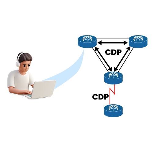
Cisco Discovery Protocol (CDP) is a proprietary Layer 2 media- and network-independent protocol designed to discover connected Cisco routers, switches, and unified communications hardware. It periodically transmits SNAP-encapsulated frames to the multicast MAC address 01:00:0C:CC:CC:CC to facilitate automated device initialization and voice VLAN provisioning.
- Native Ecosystem Integration: Automatically negotiates inline power allocation for IP phones and configures auxiliary voice VLAN assignments on switch access ports.
- Protocol Independence: Functions over non-IP transport layers, allowing administrative discovery even when Layer 3 interfaces are unconfigured or failing.
- Deployment Boundaries: Operates strictly on unrouted, directly connected physical links, dropping frames at Layer 3 interface boundaries to preserve security segmentation.
3. IP Route (L2 Interface Switching Pathways)
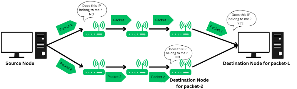
In Layer 2 architectures, IP Route references the operational bridging path mapped from local routing tables down to physical egress switch interfaces. It serves as the logical glue where network-layer destination IPs map to data-link next-hop interfaces before frame encapsulation occurs.
- Next-Hop Resolution: Binds Layer 3 routing decision outputs directly to specific Layer 2 switchport interfaces and egress VLAN tags.
- Hardware ASIC Acceleration: Programs forwarding decisions into TCAM and switch ASIC hardware tables for wire-speed frame throughput.
- SDN Controller Telemetry: Allows software-defined networking agents to dynamically inject Layer 2 flow paths based on centralized routing policies.
4. Forwarding Database (FDB / MAC Table)
The Forwarding Database (FDB), commonly referred to as the MAC Address Table, stores learned hardware addresses, associated egress ports, and VLAN IDs to direct frame forwarding across network switches. Switches continuously inspect frame source MAC addresses to populate the FDB, switching frames deterministically or flooding unknown unicast destinations.
- Dynamic Address Learning: Inspects incoming Ethernet frame headers to map source MAC addresses to physical switch ports with configurable aging timers.
- Unicast Frame Filtering: Prevents network-wide traffic saturation by filtering unicast traffic directly to the mapped destination port rather than broadcasting.
- Security & Port Binding: Supports static FDB entries and Port Security features to block unauthorized MAC address spoofing and rogue switch attachment.
5. Address Resolution Protocol (ARP)
Address Resolution Protocol (ARP) translates 32-bit IPv4 addresses into 48-bit physical MAC addresses within a local broadcast domain. When a host requires an outbound hardware address, ARP issues a local broadcast query, receiving a targeted unicast response to complete frame encapsulation.
- Dynamic Cache Mapping: Maintains a dynamic in-memory lookup table mapping protocol IP addresses to physical network interface controller (NIC) addresses.
- Gratuitous ARP Functionality: Enables hosts to advertise IP updates and update peer ARP tables instantly during high-availability failovers.
- Inspection & Mitigation Features: Integrates with Dynamic ARP Inspection (DAI) on managed switches to mitigate ARP poisoning and man-in-the-middle exploits.
6. Multi-link Trunking Protocol (MLT)
Multi-link Trunking Protocol (MLT) aggregates multiple physical Ethernet links into a single logical high-bandwidth channel to increase link capacity and provide immediate hardware fault tolerance. By distributing frames across bonded links, MLT prevents single-point-of-failure bottlenecks without triggering Spanning Tree Protocol (STP) port blocking.
- Active Load Balancing: Distributes outbound frame transmission across member links using hash algorithms based on source/destination MAC or IP addresses.
- Sub-Second Failover Converge: Automatically redistributes traffic across surviving physical links in the event of an individual transceiver or cable failure.
- Split Multi-Link Trunking (SMLT) Support: Extends link aggregation across dual physical switch chassis to eliminate switch-level single points of failure.
7. Controller Area Network (CAN Protocol)
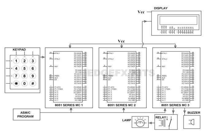
Controller Area Network (CAN) is a specialized, message-based Layer 2 serial protocol engineered to allow microcontrollers and embedded devices to communicate without a host computer. Commonly deployed in industrial automation and automotive platforms, CAN utilizes bitwise arbitration and differential signaling to deliver real-time deterministic communication.
- Non-Destructive Bitwise Arbitration: Resolves bus contention instantly based on frame priority IDs without dropping high-priority control messages.
- Built-In Error Handling: Features integrated frame acknowledgment, bit stuffing, and automatic node isolation to maintain bus integrity against industrial noise.
- Embedded Deployment Architecture: Operates over twisted-pair physical media without complex IP stacks, minimizing hardware memory and processing overhead.
8. Point-to-Point Protocol (PPP)
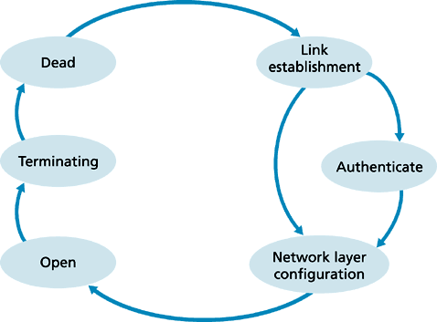
Point-to-Point Protocol (PPP) is a Layer 2 encapsulation protocol designed to establish direct communication links between two networking nodes, such as router-to-router WAN connections. PPP provides link setup via Link Control Protocol (LCP), authentication through PAP/CHAP, and multi-protocol network encapsulation via Network Control Protocols (NCP).
- LCP Link Maintenance: Establishes, configures, tests, and terminates data link connections dynamically with customizable MTU and quality monitoring rules.
- Integrated Authentication & Encryption: Supports Password Authentication Protocol (PAP) and Challenge Handshake Authentication Protocol (CHAP) for secure endpoint identity validation.
- Ethernet Adaptation (PPPoE): Encapsulates PPP frames inside standard Ethernet frames, allowing service providers to deliver authenticated access over broad broadband architectures.
Maintaining continuous visibility over these Layer 2 mechanisms across complex environments requires dedicated observability software like Site24x7 Network Monitoring to automatically discover devices, track MAC tables, and trigger threshold alerts.
Frequently Asked Questions
What is the primary operational difference between LLDP and CDP?
LLDP is an open IEEE standard (802.1AB) supported across all major enterprise networking vendors, whereas CDP is a proprietary protocol developed specifically for Cisco devices. While both perform neighbor discovery, LLDP uses standardized TLVs while CDP includes specialized hooks for Cisco IP telephony and power management.
How does a Layer 2 switch handle unknown destination unicast frames?
When a switch receives a frame destined for a MAC address not currently present in its Forwarding Database (FDB), it performs unknown unicast flooding. The switch replicates the frame out of every active port within the source VLAN, excluding the port on which the frame was originally received.
Why is Layer 2 monitoring critical for modern hybrid enterprise networks?
Layer 2 protocol issues—such as ARP spoofing, MAC table exhaustion, and link aggregation drops—directly degrade higher-layer TCP/IP routing and application performance. Automated SaaS network monitoring tools track L2 telemetry in real time to prevent network loops, diagnose hardware degradations, and streamline topology mapping.
Advertisement